8-bit binary counter circuit diagram Synchronous multisim 3 bit counter circuit diagram
[DIAGRAM] Circuit Diagram 3 Bit Synchronous Binary Counter - MYDIAGRAM
Synchronous counter circuit diagram 4 bit synchronous counter circuit diagram Solved refer to the 3-bit synchronous counter diagram.
Synchronous flop geeksforgeeks toggle
Design a 3-bit gray code counter using jk flip flopsSynchronous counter in digital electronics with circuit diagram Counter synchronous geeksforgeeks[diagram] circuit diagram 4 bit binary counter.
[diagram] logic diagram of 3 bit synchronous counter3 bit asynchronous up counter with circuit diagram and truth table Up down counter circuit diagramSynchronous counters flop flops clocked sequential inputs.

Logic diagram of 4 bit asynchronous counter
3 bit synchronous up counter on 14 thSynchronous circuit bcd mod10 flops constructed murat fig Onorevole suonare il piano pastore up down counter circuit using jk3 bit asynchronous up counter with circuit diagram and truth table.
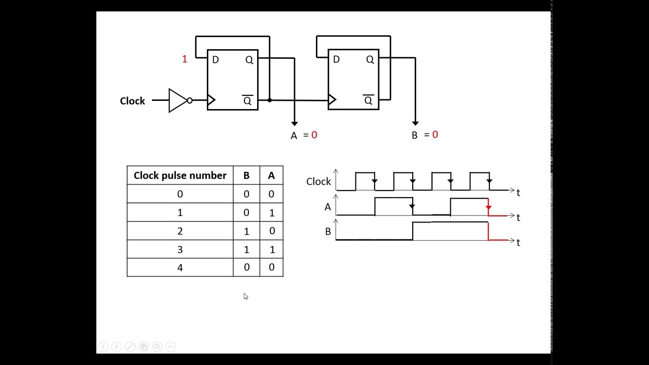
What is synchronous counter? definition, circuit and operation ofEdge qca synchronous triggered Circuit diagram of 3 bit synchronous counter4 bit asynchronous down counter circuit diagram.
3 bit synchronous down counter
[diagram] circuit diagram 3 bit synchronous binary counter2 bit binary counter circuit diagram 3 bit asynchronous up counter with circuit diagram and truth tableSynchronous flop flops.
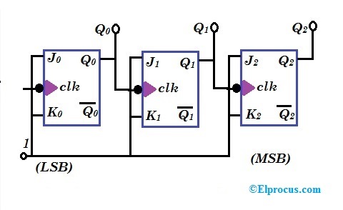
Synchronous counters using jk flipflop3 bit synchronous down counter 4 bit up down counter circuit diagram3 bit synchronous counter truth table.

17. the bcd (mod10) synchronous up counter circuit constructed with d
Synchronous 3-bit counter with negative edge-triggered qca circuitBit counter synchronous clock diagram bits rising solved output edge Design a 3-bit synchronous binary counter4 bit synchronous counter using jk flip flop verilog code.
4 bit synchronous binary counter download scientificSynchronous counters 4 bit counter truth tableSynchronous counter : circuit, working, types & its applications.

Counter circuit diagram
.
.
![[DIAGRAM] Circuit Diagram 4 Bit Binary Counter - MYDIAGRAM.ONLINE](https://i2.wp.com/www.electronics-tutorials.ws/wp-content/uploads/2013/08/cou7.gif?fit=564%2C253)

17. The BCD (MOD10) synchronous up counter circuit constructed with D

Circuit Diagram Of 3 Bit Synchronous Counter
![[DIAGRAM] Circuit Diagram 3 Bit Synchronous Binary Counter - MYDIAGRAM](https://i2.wp.com/image1.slideserve.com/3085365/four-bit-asynchronous-binary-counter-and-its-timing-diagram-l.jpg)
[DIAGRAM] Circuit Diagram 3 Bit Synchronous Binary Counter - MYDIAGRAM

4 Bit Synchronous Counter Using Jk Flip Flop Verilog Code - Design Talk
3 Bit Asynchronous Up Counter With Circuit Diagram And Truth Table
![[DIAGRAM] Logic Diagram Of 3 Bit Synchronous Counter - MYDIAGRAM.ONLINE](https://i2.wp.com/electronicscoach.com/wp-content/uploads/2019/07/circuit-diagram-of-3-bit-asynchronous-counter.jpg)
[DIAGRAM] Logic Diagram Of 3 Bit Synchronous Counter - MYDIAGRAM.ONLINE

Synchronous Counters using JK Flipflop - EEES.IN
